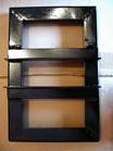
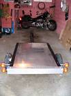
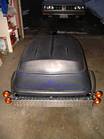
My CTC (Canadian Tire Corp.) trailer with a Thule car top carrier
This trailer is very similar to the H/F trailer and car top carrier that is being built in the US. I bought this trailer used in Niagara Falls, Ontario, Canada after it had been narrowed to fit the carrier and the tongue was lengthened 18" to take a cooler, but no cooler had been mounted. The total length of the trailer is 101". A sheet of 1/4" aluminum was used to cover the trailer before the carrier was bolted on.
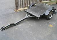
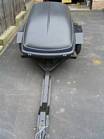
The carrier is bolted to the aluminum cover on the trailer with 8 bolts, plates and knobs that can be tightened by hand, making for easy removal.
Adding a cooler
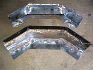
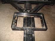
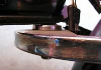
I didn't want a lot of tongue weight with a large cooler and I don't do a lot of camping so I used a small cooler I already had. I used 1 1/2" angle iron to make the cooler rack. The rack frame is one piece with the bottom part notched at each corner to allow bending the corners and make it easy to weld. In picture #2 of the bottom, you can see how the corners were cut and welded. Two more pieces of angle iron were welded to the bottom so it could be bolted to the tongue. Our plan is to make a black vinyl cover to put over the cooler after it is bungee corded onto the rack and fasten it around the bottom with velcro.
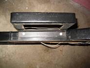

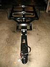
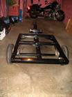
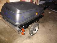
Mounting the spare tire under the trailer
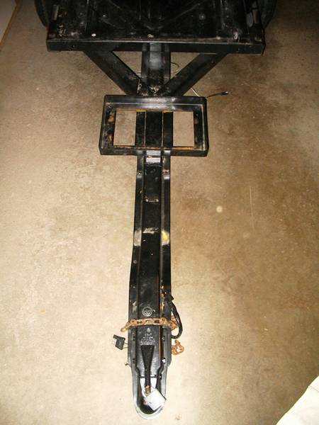
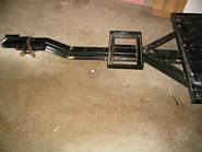
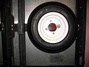
The spare tire took up too much room in the carrier so I mounted it underneath, behind the axle so as not to add tongue weight and counter balance the cooler. Since the tongue did not go all the way to the back of the trailer frame, I added two 1 1/2" pieces of angle iron and bolted the tire and wheel to the angle iron.
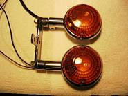
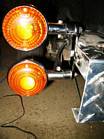
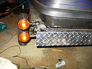
Changing to Vstar stop, tail and directional signal lights
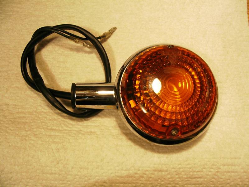
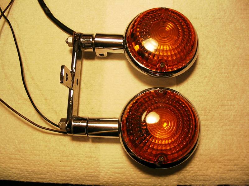
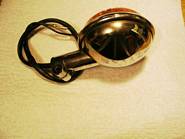
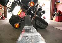
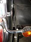
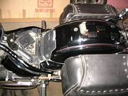
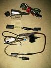
I was lucky to be in a bike shop when a custmer was having custom turn signal lights put on his Vstar. He had no use for the originals so I made him an offer and picked them up for a song. I wasn't satisfied with the look or brightness of my trailer lights so I figured Vstar lights on my trailer to match my bike, a 2001 Vstar 1100, would look good.
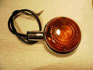
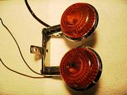
Pictures #1 & #2 show the type of light I purchased.
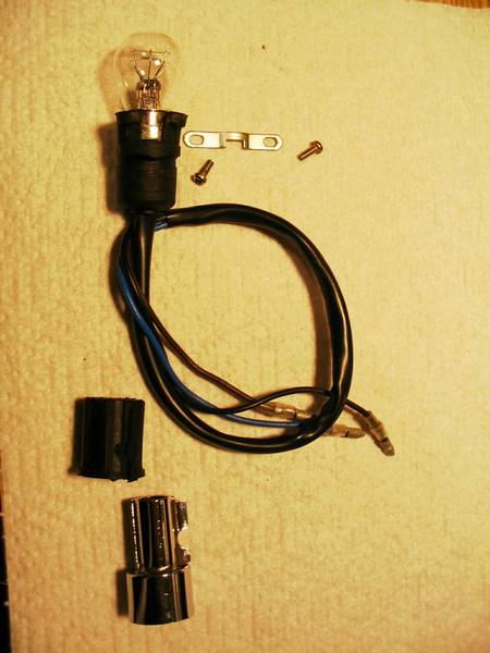
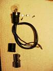
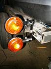
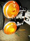
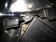
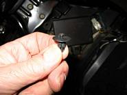
Pictures #3 & #4 show a light dis-assembled.
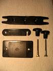
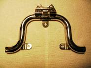
After giving a lot of thought about how I would mount the lights, I decided I needed another rear mounting assembly which I was lucky enough to find at another bike shop. My plan was to cut off the ends of the rear mounting assemblies and make a bracket to bolt them to.
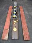
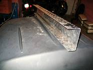
Pictures #5 & #6 show a rear mounting assembly and 2 of the ends I cut off.
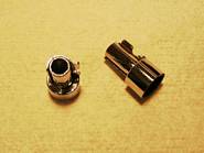
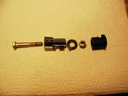
Picture #7 shows the bolt, washer and nut used to bolt the end that was cut off to a bracket. The rubber goes over the small end before it is inserted into the light assembly.
Picture #8 shows the bolt beside the mounting end and how much had to be cut off to make room for the head of the bolt inside the light stem.
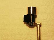
Pictures #9 & #10 show how a hole was drilled in the light assembly to allow the wires to be re-routed outside the light stem. The wires used to go through the centre of the light stem and mounts, but now this space is used up by the bolt to mount the lights to the new brackets.
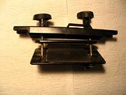
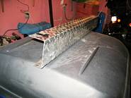
Pictures #11 & #12 show the completed assemblies attached to the new brackets I made. The brackets are made from 1"x1/4"x5" steel with a 1/2"x1/8"x2" tab welded to it which I had chromed. Getting them chromed was the most expensive part of the whole light project. Stainless steel bolts were used to mount the new light assemblies.
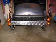
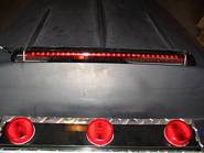
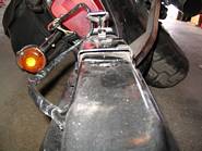
Pictures #13, #14 & #15 show the lights mounted on the trailer.
It is illegal in Ontario to have an amber stop light so I will be replacing the stop and tail light lenses with red lenses used on Harley bikes.

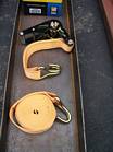
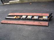
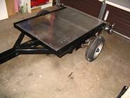
Adding a bike rail to the trailer
I had a rail made up to fit the trailer without the carrier so I can use the trailer to haul my bike. A local parts supplier had 1 1/2" ratchet straps on sale for $10.00 Cdn each and the rail cost me $50.00 Cdn to have made, so the whole kit cost me about $100.00 Cdn or $120.00 US. I scrapped an old picnic table so the 2"x8"x8' seats will make good ramps.
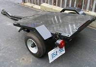
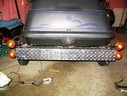
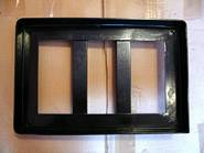
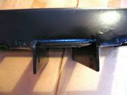
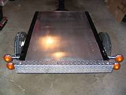
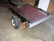
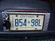
Checker plate rear bumper.
I had a piece of 1/8" checker plate cut and bent to cover the rear of the trailer. I figured this would dress it up and also makes it more visible at night because it reflects the headlights from the cars behind me.
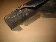
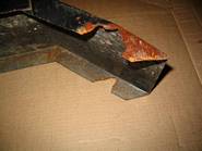
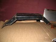
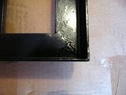
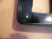
Fenders before the repairs.
One fender fell off on my east coast trip June of 2005. I made a temporary repair to get home and then took a closer look at both fenders and discovered they were both close to falling off.
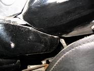
Pictures #1-#3 show the fender that fell off. The top lip with the most damage is the one that broke on the east coast trip. The bottom lip shows the damage that had happened since then, since all I did was reverse the fender and drill new holes. The broken pieces fell off when I removed the fender. Luckily, there were big washers under the nuts that were still clamping the fender to the trailer.
After inspecting the other fender, I could see there were stress cracks on it already. Both fenders need to be repaired or replaced and then I will mount them lower so there is less space between the tire and fender to look better and less chance for them to vibrate and crack the metal.
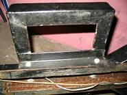
Cooler rack painted
Frame painted & cooler rack added

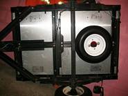
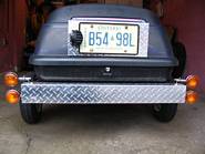
New lights, checkerplate bumper and aluminum bed installed.
Carrier installed.
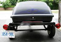
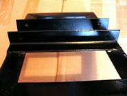
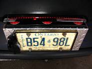
Checker Plate licence plate holder.
The licence plate used to be mounted under the left tail light, which is now gone. This was a pain because it scraped the ground if the tongue was lifted too high when moving the trailer around. I had a piece of 1/8" checker plate cut and bent with a lip 3" wide on the top. The lip would hold a 3rd brake light from the junk yard and an LED licence light is mounted beside the licence which is now covered with a clear plastic cover. I wanted to mount the licence light above the licence but it didn't look or fit the carrier shape right.
Murphy strikes again!!.
Now it's wiring problems. I went from single, stock trailer lights with LED lights in them, but they were wired up without a brake light and used an LED third brake light off a car for the brakes. I have tail, brake and signals in my new Vstar lights but wanted to retain the third brake light.
Problem #1. The old LED third brake light will not come on when wired to the Vstar brake light, yet it works fine when connected straight to a 12v source. Yes, the polarity was correct! I got around this problem for now by using a bar with 3 LED clearance lights mounted on it as the third brake light since they seem brighter than the tail lights. I have ordinary bulbs in the Vstar lights on the bike and on the trailer now. When I find time, I'll put the LED's in lights in the new trailer Vstar lights and see what happens.
Problem #2 is that the licence light, when wired to the tail lights, blinks when either directional signal is on. I got around this problem by wiring the licence light directly to a 12v source that I already had wired back to the carrier to power accessories in the carrier.
Problem #1 bugged me too much to leave it the way it was. The old trailer lights had LED bulbs in them but I thought they faced the wrong way to give the best lighting, so I didn't use them on the new lights. Big mistake. I put the LED bulbs in the lower Vstar lights for the stop and tail (uppers are for turn signals) and now the LED 3rd brake light works fine. For some reason it wouldn't work with the ordinary filament bulbs. Don't know why and don't care as long as it works!
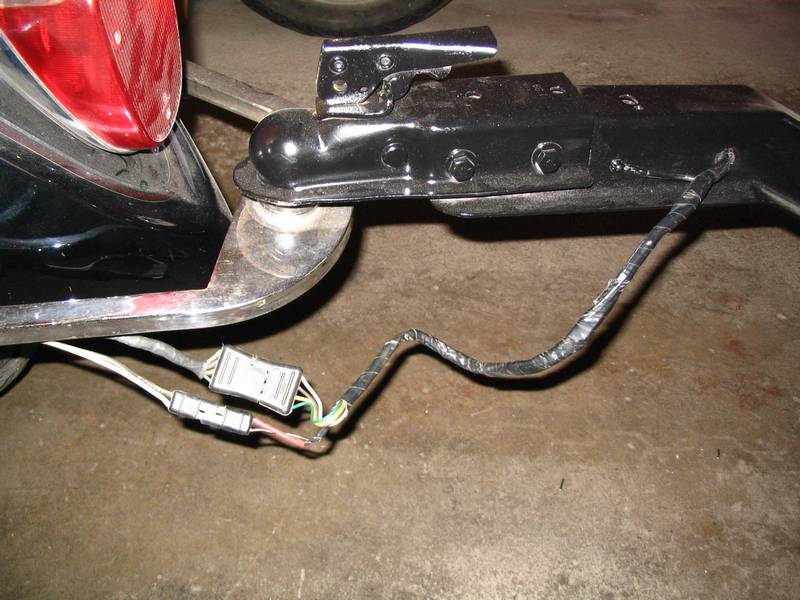
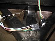
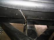
Flat 4 prong plug for wiring that goes to the carrier lights
I wanted to be able to remove the carrier if need be but the licence and 3rd brake light had wires running to them. Because the carrier hinges at the front it was best to feed the wire in from the front of the carrier and along the top to the back where it exits to the lights. I used a flat 4 wire plug and positioned it so it sits just inside the carrier.
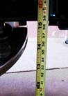
When does the tongue start to twist?
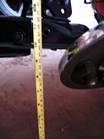
There has been a lot of talk about conventional vs swivel hitches. I decided to see how laying my bike down would affect the hitch and tongue of my trailer. The first 7 pictures show the bike resting on the floor board which is over a lot farther than it would be if the floor board just scraped on a turn. I guess I should have checked it just as the floor board touched.
The tongue twist was 1/2". It measured 11" on the high side and 10 1/2" on the low side.

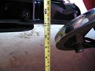
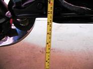
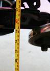
When the bike was laid all the way over so it was resting on the engine guard and saddle bag, the tongue twist was 1". It measured 9 3/4" on the high side and 8 3/4" on the low side.
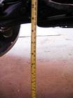
With the bike sitting on the kick stand, the tongue height was 16" on each side.

Now I am satisfied!
Well, curiosity got the best of me. After playing with a jack stand under the passenger foot peg, I had the bike tipped over so the floor board was only 1/2 " off the ground. At this point, the tongue was still level at a height of 15 1/4". There was still a little play in the hitch and it looked like it could go over maybe another 1/8" before it would start to bind and start twisting the tongue. Anytime I have scraped the floor boards it has just been for a second or two as my reactions automatically cause me to correct so I don't figure I have a problem with my hitch set-up.
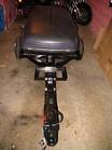
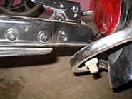
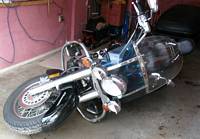
Modified trailer hitch
My trailer was pulled behing a mid 80's Goldwing and I was given the Goldwing hitch when I bought the trailer. It had no mounting hardware with it. The first thing I did was fit it to see how the clearance was. I had to spread the arms out a bit at the ball end, then bend them back in around the axle and final drive unit. This didn't require any special tools, just old fashioned muscle power. The hitch is made of chromed square tubing with a piece of flat steel at the end of each arm.
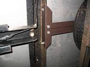
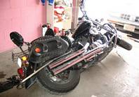
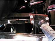
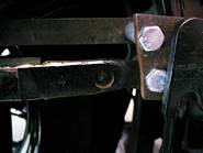
Pictures #1 & #2 show how I had to lengthen this piece to make it reach the lower foot peg bolt. You will also notice I made up a steel plate to move the passenger foot peg out and forward for a more comfortable position, but I still used the original lower foot peg bolt to mount the hitch. The upper foot peg bolt has the bag brackets fastened to it.
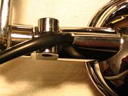
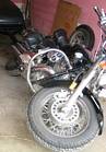
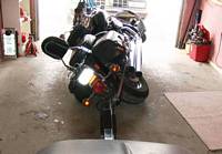
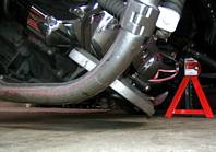
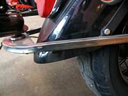
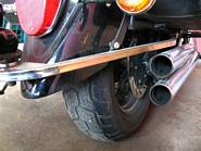
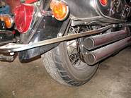
Pictures #3, #4, & #5 show how the hitch sits relative to the exhaust, bags and rear fender. You can see where I welded a small tab on each arm for the rear mount. Picture #6 is a little hard to see but you can see the piece of flat steel that runs from the tab on the hitch to the rear bag mounting bolts. A small bend at the hitch end and half way up made these pieces fit comfortably around the bags. This hitch is solid as a rock. After I did this I saw a hitch (make unknown) on a Road Star that was made exactly the same way.
Having the parts I made and the hitch re-chromed was beyond what I was willing to spend so I opted to paint the new brackets black so they would blend in with everything else around them that is black.
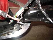
Bike wiring for trailer lights
Picture #1 shows seats removed.
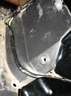
Picture #2 shows the triangular piece of plastic that must be removed to get at the wiring to the rear lights. The bottom 2 plastic fastneners have been removed and the screw driver points to the top one that is still in place.
Picture #3 shows the fastener with the centre post pushed in about 1/8". Don't push too hard or you will push it all the way through and probably not find it. Now you can lift the fastener out.
Picture #4 shows the fastener after it has been removed. The post must be pushed back out about 1/8" to be able to re-insert it later. When the fastener is re-inserted, puch the post in so it is flush with the top of the fastener.
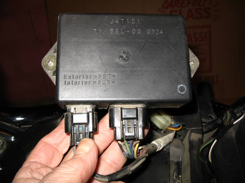
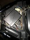
Picture #5 shows the rectangular ignition module that must be removed before the plastic cover can be removed. Remove the 2 screws to lift it up.
Picture #6 shows the module removed from the cover. Now remove the wiring plugs by pushing down on the tab with your thumb and pull the plug out of the module. Repeat for the second plug.
Picture #7 shows the hole in the triangular plastic cover that the wires must be pushed through to remove the cover.
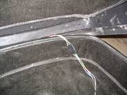
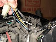
Picture #8 shows the 5 wires coming from the white plug that go to the rear lights. I spliced into these wires, in the section that is taped, to attach the wires going to the trailer.
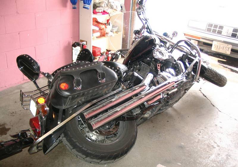
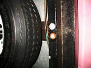
Picture #9 & #10 show how the wires to the trailer are routed across under the seat and are fed through under the fender where they go to the hitch arm and follow it to the back of the hitch.
Picture #11 shows the trailer attached and the wires connected to the trailer. I ran separate wires for the tail, stop and signals using the 4 prong flat plug. I wanted a ground and separate 12v power wire to the trailer so I used a 2 prong flat plug for these 2 wires.
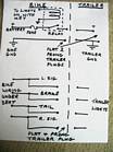
Picture #12 shows my wiring schematic.
Colour Codes for Vstar 1100 Bike Wiring:
Black = Ground (I didn't use this wire. I used frame ground at my hitch)
Green = right signal
Yellow = brake light
Brown = left signal
Blue = tail light
I suggest using a 5 prong plug so the ground is included. That way you are not relying on the hitch to provide the ground connection. Some people like to grease their ball. This is too messy for me so I use waxed paper from the kitchen. I take a square piece and fold it so that it covers the ball, then put the coupler on top of the waved paper. When I take the coupler off, the waxed paper stays in the coupler, so I take it out and put it on the ball first when I re-connect the trailer. That way the waxed paper is always in the coupler.


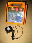
My booster Pac
I have a lot of 12 volt accessories so I decided to carry a battery in the trailer. I found a booster pac on sale at CTC that had booster cables on it. This would also let me use it to jump start my bike if needed. The booster pac can be charged by the bike while travelling or at night with a 110 volt power pack.
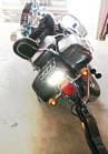
Picture #1 is a front view of the booster pac.
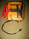
Picture #2 is a back view of the booster pac with a cable I made up to attach accessories using a flat 2 prong trailer plug.
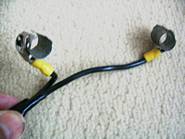
Picture #3 shows the clips I made to slip on the back of the booster pac where the cable clamps clamp on for storage. This makes a better connection than using a cigarette lighter plug on the front that can jiggle loose.
Picture #4 shows a cigarette lighter socket, jumper with a diode and a 2 position, centre off switch with a resistor to for giving 2 heat settings for my 12 volt gloves.
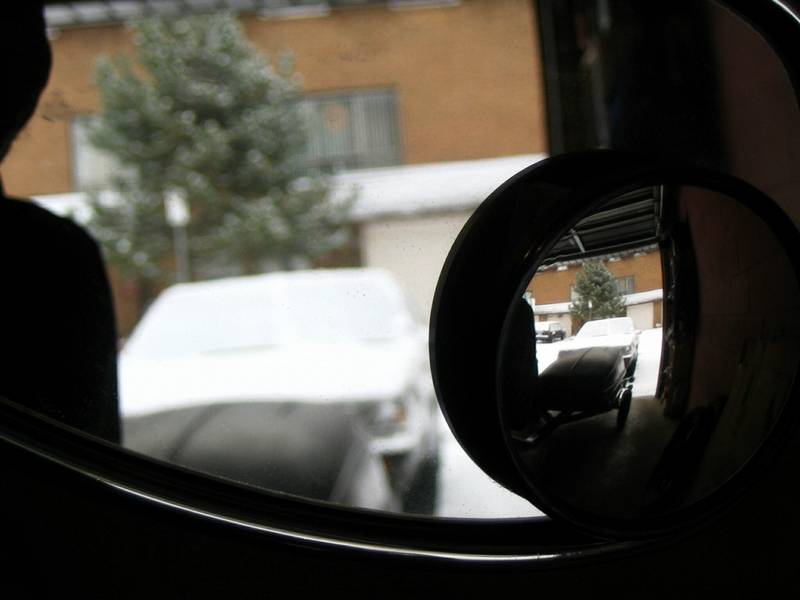
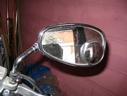
Adding a spot mirror to the bike mirrors
I was curious about the affect of adding spot mirrors for increased visibility, mainly for checking the blind spot even though I do make shoulder checks. They are effective but in my opinion, do not replace a shoulder check. It's just extra insurance for making sure my "space" is not being invaded.
Where I did notice a big difference was when I was pulling the trailer.
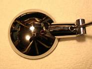
Picture #1 shows where I found the best location for the spot mirror.
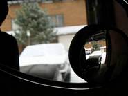
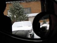
Pictures #2 & #3 were interesting to take as the mirrors change the focusing affect on the camera.
Picture #2 shows the trailer in focus in the spot mirror.
Picture #3 shows the trailer in focus in the bike mirror. When comparing the 2 pictures, you can see how the trailer wheel is visible in the spot mirror and not the bike mirror. This gives me a good view of the exact position of the trailer wheels.
Last job is repairing or replacing the old fenders.
We just had a big snowfall so it's time to put the trailer in the back yard and wrap it up for
the winter. I can work in the garage on the fenders without needing the trailer in there.
Finally it's spring, so it's time to get the fenders repaired.
I didn't see any fenders that I liked the looks of or the price of, so I'm repairing the old ones. I
made a wider lip on the inside of the fender to stop the carrier from being splashed and also to
look better so there won't be a space between the top of the fender and the trailer bed.
Picture #1 shows the fenders after the welding.