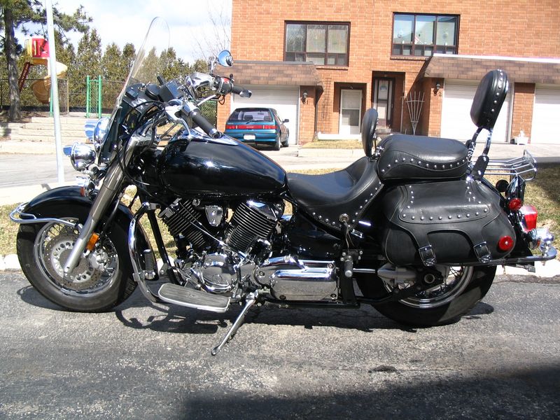
My 2001 Vstar 1100
2001 vstar 1100
This was my third bike, bought used September 11th, 2003 with only 1,700 km's
on it. Most of the accessories were already on it. I added Yamaha hard leather
bags and a Mustang seat with driver backrest. I still planned to ride through the
winter on dry days but didn't put the heated grips on. At the December bike show
in Toronto I bought a pair of Widder heated gloves and have been very satisfied
with them. I provided several 12v sources at the handlebars, some live all the
time and some live just with the key on. My GPS and heated gloves are the main
reason for this extra power.
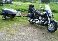
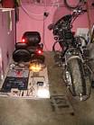
The summer of 2004 I bought a trailer and modified the Honda Goldwing hitch that
came with it to mount on the Vstar. As of the end of 2005, I have put over 67,000
km's on this bike. It handles great riding 2 up pulling the trailer.
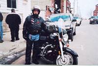
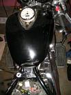
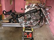
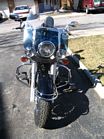
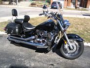
Picture #1 was taken about a week after I got it before heading up to Port severn.
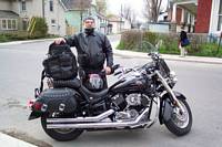
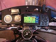
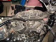
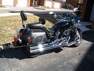
Picture #2 was taken after I added a set of Yamaha hard leather bags.
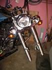
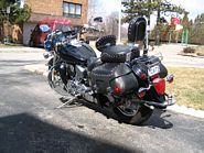
Picture #3 was at Port Dover Feb. 13th, 2004.
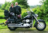
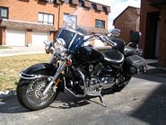
Picture #4 was May of 2004 at my Daughter's in Kingston.
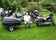
Picture #5 was at Port Severn Sept. 2004.
Pictures #6 & #7 were in Upper Stewiacke, Nova Scotia during our east
coast trip the summer of 2005.

GPS, Gauges and wiring
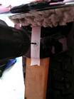
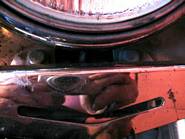
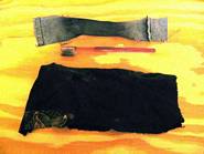
Picture #1 shows a panel I made out of 1/4" plywood to fit between the
windshield and handle bars to mount my GPS, volt and ammeter gauges, thermometer,
cigarette lighter socket and a couple of switches, then covered it with black
vinyl. Everything permanently mounted on the panel is wired to the key.
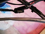
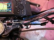
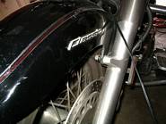
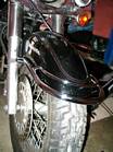
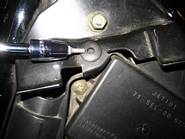
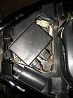
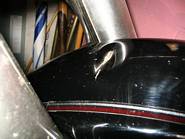
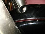
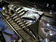
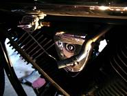
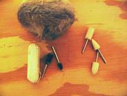
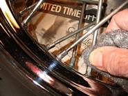
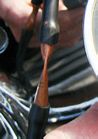
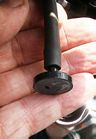
Pictures #2 & #3 show the flat 2 prong trailer plugs that supply power
all the time to the GPS and my 12v gloves. The plug that is used for my gloves
is also used to plug the battery tender in.
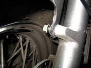
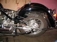
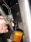
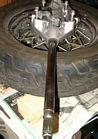
Installing a front fender rail
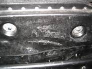
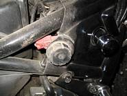
Pictures #1 & #2 show the front bolts that must be removed to instal the rail.
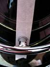
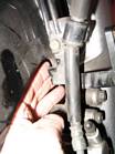
Picture #3 shows a piece of masking tape on the fender where the front
of the rail is fastened to the fender. Trace around the post onto the masking
tape, then lift the rail and put something soft under it to hold it up while
drilling the hole.
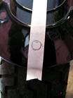
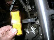
Pictures #4 shows the centre of the circle centre punched. Put a piece
of wood between the fender and tire so as not to drill into the tire.
Pictures #5 shows drilling a 1/8" starter hole.
Pictures #6 shows the final 7/32" hole drilled.
Pictures #7 shows the installation completed.
Adjusting the rear spring preload
According to the manual, as you look down on the shock, turning the ring nut
CCW (going to a higher number) increases the spring preload, making the suspension
harder. There are 7 numbers to select. The minimum is 1 (soft) and the maximum is
7 (hard). The tool kit contains the ring nut wrench. I found I had to use a long
bar to get enough leverage to turn the ring nut.
According to my thinking, adjusting the preload the way they say is backwards.
Adjusting to a higher number is supposed to make it harder, but it lengthens the
spring. I think lengthening the spring allows more travel, which makes it softer.
My bike was set on number 2 and I changed it to 6. I am going to change it back
to 3 and see what the difference is. I suspected I was bottoming when riding 2 up
but I can't see any marks on the swing arm to indicate this. I have been told it i
s probably the shock hitting the travel limit. I didn't find pulling the trailer
made any difference.
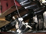
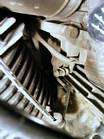
Picture #1 shows seats removed.
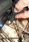
Picture #2 shows the triangular piece of plastic that must be removed to get at
the spring. The bottom 2 plastic fastneners have been removed and the screw driver
points to the top one that is still in place.
Picture #3 shows the fastener with the centre post pushed in about 1/8". Don't
push too hard or you will push it all the way through and probably not find it. Now you
can lift the fastener out.
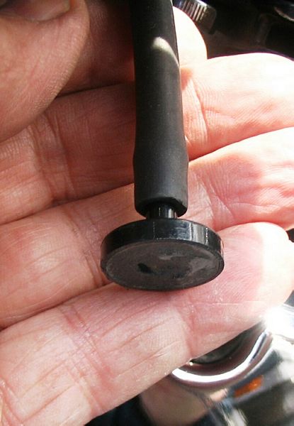
Picture #4 shows the fastener after it has been removed. The post must be pushed
back out about 1/8" to be able to re-insert it later. When the fastener is re-inserted,
push the post in so it is flush with the top of the fastener.
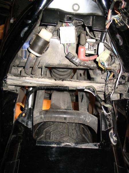
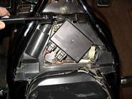
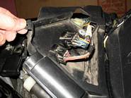
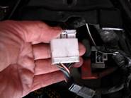
Picture #5 shows the rectangular ignition module that must be removed before the
plastic cover can be removed. Remove the 2 screws to lift it up.
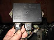
Picture #6 shows the module removed from the cover. Now remove the wiring plugs
by pushing down on the tab with your thumb and pull the plug out of the module. Repeat
for the second plug.
Picture #7 shows the hole in the triangular plastic cover that the wires must be
pushed through to remove the cover.
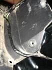
Picture #8 shows the mud flap before being removed.
Picture #9 shows the mud flap removed.
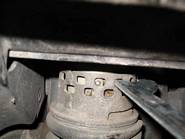
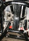
Picture #10 shows the ring nut wrench on the ring nut and the shock in position
6. This is a "fit by feel" proceedure as there is very little room to work around the shock.
Picture #11 shows the shock changed to position 3.


Paint Job
It's time to strip the bike down and clean it up. I'll remove the fenders, side
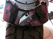
panels and gas tank to have them painted. The front fender has a deep dent in it
from the light bars when they fell off last December when I took Pat for her first ride.
The bolts sheared off so I replaced them with grade 8 bolts. I figure the East Coast
trip to Nova Scotia in 2004 was the cause of the excess stress on these bolts from the
"pot hole" roads we rode on there.
Damaged front fender
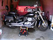
Stripping it down for paint
I did this after changing the rear spring preload so these pictures continue after
pictures #1 to #9 above under "Adjusting the rear spring preload".
Pictures #1 & #2 show the 2 bolts on the side and 2 bolts on the bottom that
hold the left bag on. The rear bolt has been removed in the 2nd picture.
Picture #3 shows the left side bag removed.
Picture #4 shows the left side bag bracket removed.
Picture #5 shows the right side bag, bracket, backrest and battery cover removed.
Picture #6 shows the left side bag, bracket, backrest and tool storage cover removed.
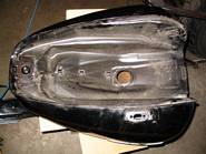
Picture #7 shows the rear fender removed.

Picture #1 Remove the front 2 fender bolts first.
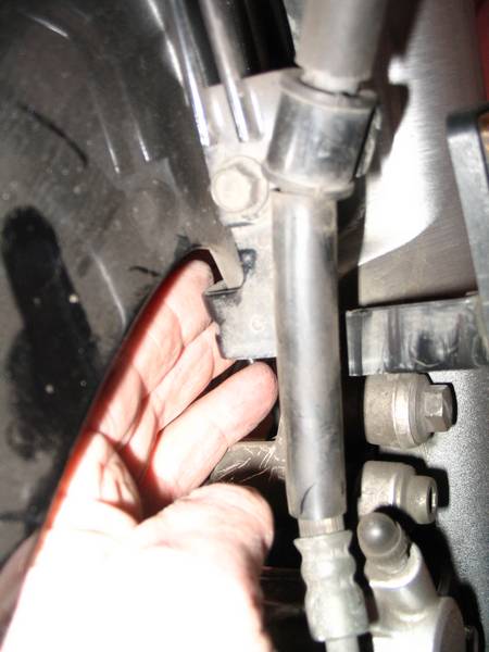
Picture #2 Before removing the back 2 fender bolts, remove the bolts holding the
front brake line to the mounting bracket. Pull the brake line out away from the fender.
Picture #3 Remove the 2 rear fender bolts. These are hard to get at.
Picture #4 Remove the brake line bracket and reflector.
Picture #5 Carefully slide the fender forward to remove it. I recommend covering
the fender to prevent scratching it when removing it. I didn't because I was removing it
to have it painted
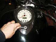
Pictures #1 & #2 show removing the speedometer (3bolts).
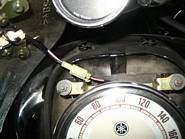
Picture #3 shows disconnecting the neutral light wire. Push the tab towards
the wires and pull the plugs apart.
Picture #4 shows removing 2 bolts at the rear of the gas tank.
Picture #5 shows making sure the gas is off.
Picture #6 shows pinching the gas line clamp to move it up the hose out of the way.
Picture #7 shows the gas line disconnected.
Picture #8 shows disconnecting the speedometer wiring harness. Push the tab and pull the plugs apart.
Picture #9 shows the rubber bumper that the gas tank slides into for
mounting. Straighten the front wheel so the tank will clear the handle bars. Lift the
tank from the back and wiggle it sideways while pulling it back. It will slide back
about 2 inches then lift the front up and remove the tank.
Picture #10 shows air box that sits under the tank.
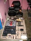
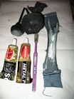
Pictures #11 & #12 show all the parts I removed and the tools I used. I like
to lay everything out in order as I take it apart and also keep the tools out that I
used in taking it apart.
Now it's off to the paint shop for a new coat of base clear black.
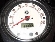

How Reserve works
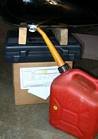
Picture #1 My tank was about half empty when I removed it so I sat it on a box and
let it drain into a small 10 litre gas can. I put it on PRI and let it drain until it
stopped, checked the amount of gas in the can, then switched to RES and let it finish
draining. I picked the tank up a little and moved it around so the gas would run towards
the shut off valve. My manual says reserve leaves 4 1/2 litres in the tank and that's
about what I drained out after switching to reserve.
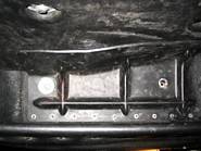
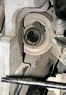
Picture #2 After removing the fuel valve shut off valve there were only a few drops
left to drip out. When reserve it empty, that's it! You can see the 2 round bolt holes and
the rectangular hole where the tubes of the shut off valve extend into the tank.
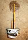
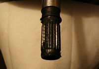
Picture #3 You can see the 2 fuel pick up tubes on the fuel shut off valve. The long
one is for the PRI position and the short one is for the RES position. Each tube has a fine
mesh filter on the end about 1" long. On the reserve tube, the filter goes right to the
plate that is mounted to the tank so it will pick up every last drop.
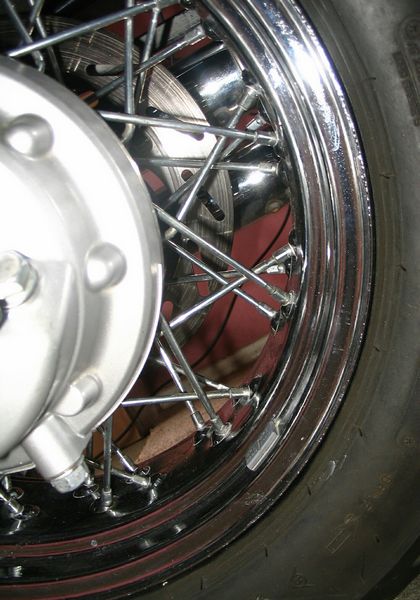
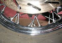
Cleaning the Wheels
Since the bike is apart to have the fenders and tank painted, this is the best
time to clean the wheels. Two years of riding in the winter has done a number
on some aluminum parts and especially on the spokes.
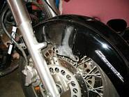
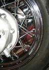
Front Wheel
I removed the front wheel by removing the locking bolt and axle nut, then pushed
the axle out. The bike was positioned on the jack stand with the wheel just touching
the ground. Once the axle was out I rasied the jack and slid the wheel out, letting
the rotors slide down out of the calipers.
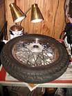
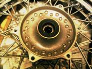
Picture #1 shows the wheel without the rotors, supported by 2 pieces of wood
and a set of desk lamps to provide good lighting.
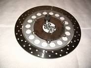
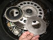
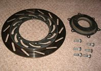
Pictures #2 & #3 show a wheel hub with a rotor removed and a rotor with 6 bolts
and a spacer.
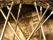
Picture #4 shows how tarnished the spokes are from the winter salt.
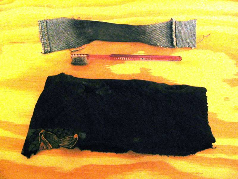
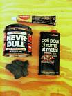
Picture #5 shows the polish, Never Dull, Autosol and 0000 steel wool that were
used to clean with.
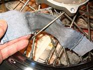
Picture #6 shows a narrow piece of denim that I used to clean the back side of
the spokes. I tried cotton from a tee shirt but it rolled up from pulling it back and
forth. I also thought the denim might be a little more abrasive for better cleaning.
Picture #7 shows a 3" buffing pad on a drill and compound but this really didn't
seem to work. I also tried some small felt buffing tips on a dremel with the compound
and Autosol. This probably did some good but it was pretty tedious work and maybe best
suited for final touch-up for whatever residue is left. Running the dremel too fast
caused the felt tip to disintegrate rapidly and the compounds sprayed off the tip.
Picture #8 shows using 0000 steel wool to clean the spoke nipples. It also
helped take the initial coat of dirt off the spokes
Picture #9 shows how the denim was used to clean the back side of the spokes.
Picture #10 shows using a toothbrush with a cloth over the bristles to polish the
spoke nipples with Autosol.
Picture #11 shows the rubber damper that is on the inside of the right side rotor centre.
Picture #12 shows the front of the bike all cleaned up reader to put the fender and
front wheel back on.
I found the Autosol to be the best cleaner with the toothbrush and 0000 steel wool to clean
the initial dirt off.
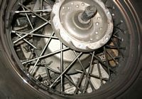
Rear Wheel
I removed the rear wheel by removing the rear caliper and hanging it out of the way
with a piece of wire. The final drive unit has 4 bolts to be removed and the axle
nut. The right side has a cap around the axle held on by 2 nuts and a bolt on the
brake caliper arm. The wheel and final drive unit with driveshaft can now be pulled
back until it is free of the frame. With the fender off this is easy, but with the
fender on, the bike must be lifted a lot higher. My jack didn't go quite high enough
so I slide the assembly in from the side when I put it back together.
Re-assembly is more difficult as the driveshaft must be put into the universal joint,
then the brake caliper arm has to be positioned as the axle is aligned in the frame
slots and keeping the washer between the frame and brake caliper arm. A little tricky
with a few things to line up at the same time but after a few trys, not really
difficult. Don't forget to grease the drive shaft before re-assembly. The dealer
reccommended wheel bearing grease but not too much or it will be thrown out as there
is not a real tight seal around the shaft.
Picture #1 shows the rotor removed and the rubber damper which is thicker than on the front wheel.
Picture #2 shows the brake caliper removed and hanging out of the way.
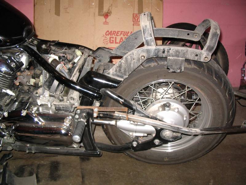
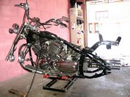
Pictures #3 & #4 show the bike stripped down as far as I wanted to go.
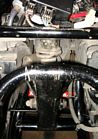
Pictures #5 & #6 show where the driveshaft goes and the seal around it.
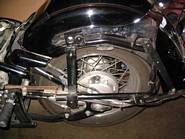
Picture #7 shows the shock adjusting ring, spring and lower mounting bolts.
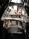
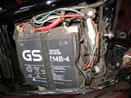
Picture #8 shows the battery and extra wiring I have added for accessories.
Picture #9 shows the cleaning tools I used on the back wheel.
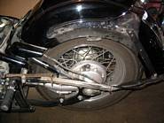
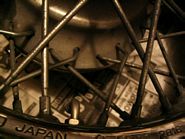
Pictures #10 & #11 show the damage done fron the winter salt.
Picture #12 shows the splines on the end of the driveshaft that need to be greased.
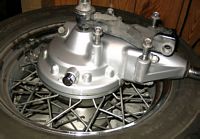
Pictures #13 & #14 show the final drive unit and the 4 bolts that hold it to the frame. The
dirty black metal bracket is the brake caliper arm that goes on the other side of the final drive
unit. I put it on this side to hold the unit together while I was cleaning it.
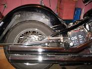
Pictures #14 & #15 show the rear wheel after cleaning. It's better but not new looking any more.
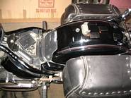
The finished bike, after new paint and cleaning

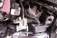
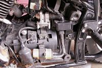
Synchronizing the Carbs
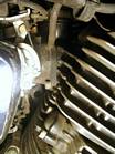
Picture #1 Shows the adjusting screw for synching the carbs.
Picture #2 Shows the vacuum hose on the left side where the carb bolts to the rear cyclinder.
Picture #3 Shows the vacuum hose on the right side where the carb bolts to the front cyclinder.
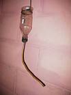
Picture #4 shows a plastic pop bottle that I fastened a small length of copper tubing to and a coat
hanger to hang it from the handlebar. I used a 2 part compound called PC 7 from Home Hardware to fasten the
coat hanger to the bottom of the bottle before I cut the bottom out and to fasten the copper tubing to the
plastic cap.
Picture #5 Shows the 1" piece of copper tubing that I used as a restrictor. I pinched the centre
closed with a pair of vise grips until the vacuum gauge only flickered 1" of vacuum.
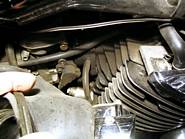
Picture #6 Shows the plug I used on the hose coming from the carb base. I split a one way
vacuum valve in half and plugged the ends. Golf tees could also be used. I just remove a plug to connect
the gauge. Now I don't have to remove the tank or any other parts to do the synch.
Picture #7 Shows the vacuum gauge, home made restrictor and white reducer to connect the gauge
after the plug was removed from the end of the hose coming from a tee at the carb base.
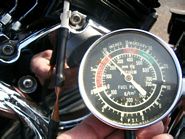
I used the same gauge to synch both carbs by moving the gauge back and forth from one side to the other. A bit
of a pain, but it got the job done and the whole set-up cost me $0.00 using parts I already had.
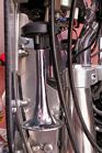
Air Horns
I had installed 2 air horns on my light bar but they didn't have any covers over the front
to stop the rain from getting into them. I guess the rain on our Route 66 trip was too much
and they stopped working. When I got home, I gave each horn a blast with my shop air compressor
and about 1/2 ounce of water came out of each horn and they started working.
I decided to mount them behind the windshield to protect them from the rain. I removed the AIS parts
that weren't being used anymore from behind the left side cover and mounted the compressor there. Now
everything should be out of harm from the rain.

Tank Bib and Fender Tips
After the paint job, I became paranoid about scratching my tank. Because of the driver
backrest, I find it easier to get on from the right side but my chaps tend to brush
across the tank, leaving small spider-like scratches on the clear coat. I found a tank
bib at the April bike show with a large pocket on it that was perfect for keeping my
leg up away from the tank.
I also figured "Murphy" would visit me if I didn't protect the rear fender tips so I
ordered both tips from Stadium Yamaha in Texas at half the price they want here.